Dense and sparse data within a single event
A stratigraphic event can be represented by both dense and sparse data representations. Dense data representations are tri-meshes, 2D grids, polyline sets and point sets (*); markers are sparse data representations. Dense and sparse data are handled differently by the gridder: surfaces based on dense data are constructed before surfaces based on markers (see The building sequence of surfaces in the 3D structural model). In case an event has both dense data and markers, in the construction sequence the event is treated as 'dense'. Assigning events that are represented by both dense and sparse data is fully supported by the application. See image below of the Assign Data form, where all events except LGS4_base have dense data (a 2D grid) as well as markers.
(*) A point set is 'dense' unless it has been set to 'sparse' by unchecking the checkbox 'Point set is Dense' on the Edit Model form of the Structural Modeling workflow. Once the point set is set to 'sparse', in terms of the construction sequence it is treated the same way as markers. For the readability of this topic, 'sparse data' will be referred to as 'markers' as this is by far the most common occurrence of sparse data.
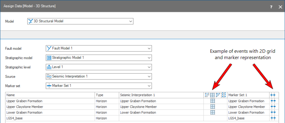
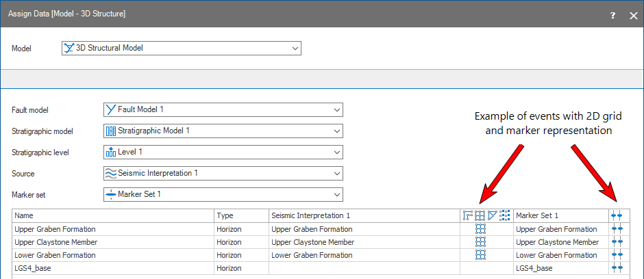
Events with both dense and sparse data representations can be assigned to the structural model and will be honored by the gridder during surface construction. click to enlarge
Conflicting data
When entering the Structural Modeling workflow, TVD differences between data representations that are geographically close to each other (or overlapping) should be limited. Examples are dense data with one or more markers nearby (or overlapping), or multiple markers laterally close to each other. When a significant difference in TVD depth exists, this is considered 'conflicting data' and indicative of poor data interpretation. Conflicting data should have been resolved during the data preparation stage, preferably via re-interpretation of your data. Preferably a depth well matching with the Depth Well Matching tool of the prepare > Post-Processing strip has been performed before entering the Structural Modeling workflow.
When conflicting data occurs nevertheless, the gridder will construct the surface by filtering out some dense data around the location of the well marker. More specifically, dense data in the stack where the marker occurs and the eight surrounding stacks will be filtered out. During surface construction, the gridder will ignore the dense data in these stacks and will try to honor the marker.

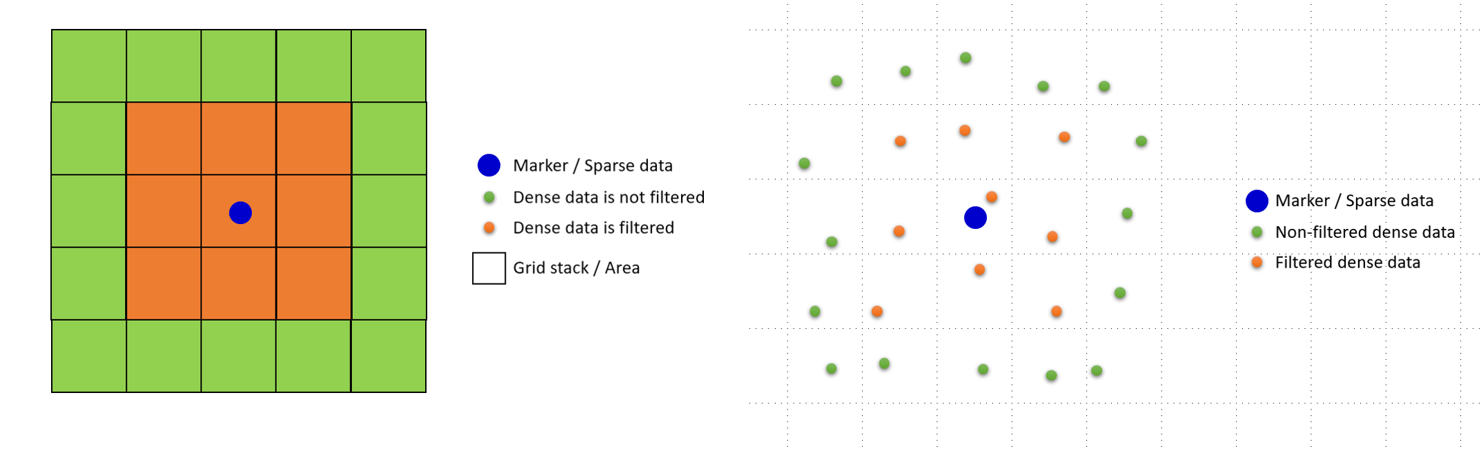
If there is dense data and a marker in the same stack, the dense data in that stack and eight surrounding stacks is filtered out (ignored by the gridder) so that the marker can be honored. click to enlarge
Alternative ways
Only in exceptional cases the filtering can cause a noticeable difference in the geometry of the constructed surface compared to the original (dense) input data, such as a local pull-up or a spike in the throw of a fault. This could for example occur when the dense data is very pronounced, e.g. shows strong bends/curvatures. Locally filtering out this pronounced dense data, the gridder would return a more 'smoothed' surface when honoring the marker. In case you want to fully honor you your dense input data (i.e. prevent filtering out of any dense data) and depending on your situation, you can try the following:
- Exclude the particular marker(s) from being used (**), i.e. model the surface with dense data only. If all your markers are affected, an easier alternative would be not to assign the marker set to the structural model at all.
- If you want to fully honor the dense data and the marker(s), first construct the structural model with the Structural Modeling workflow without honoring the particular marker(s)(**). Export the surfaces to a Surface Set and perform the final well matching with the Depth Well Matching tool in the prepare > Post-Processing strip.
- Change the resolution (make it finer) on the Set Modeling Parameters form. The stacks will be smaller, resulting in less data being filtered out.
(**) You can in/exclude markers in well matching via the 'Use for modeling' column in the Marker Table; if the 'Use for modeling' checkbox is unchecked the marker is excluded from being used in modeling operations.